Creating Diagrams appropriate to contexts with PlantUML
January 27, 2022
In this DevOps world deployment diagrams help document not just how a system relates to other components, but how the underlaying infrastructure configuration is structured.
For example, if your application requires a database and a storage bucket on a cloud provider, that requires configuration in a cloud account.
The problem with these diagrams is that they tend to show an undifferentiated experience. The diagram is produced by a DevOps engineer and then shown to other stakeholders. And too often the response is, “Ok, but where’s this thing I care about?”
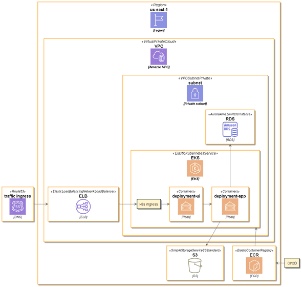
Let’s take a simple diagram of AWS services that uses everything involved with hosting a Docker container on Elastic Kubernetes Service, stores something in a S3 storage bucket, interacts with a MySQL database through the Relational Database Service, and is exposed to the Internet. Yes, this is a simple diagram, as far as these go, AWS diagrams get complicated.
Using AWS Icons with PlantUML
I generated this diagram with PlantUML and the AWS Icons for PlantUML.
Here’s the source code for this diagram:
@startuml

!define AWSPuml https://raw.githubusercontent.com/awslabs/aws-icons-for-plantuml/v11.1/dist
!includeurl AWSPuml/AWSCommon.puml

' Uncomment the following line to create simplified view
' !includeurl AWSPuml/AWSSimplified.puml

!includeurl AWSPuml/Compute/all.puml
!includeurl AWSPuml/ApplicationIntegration/APIGateway.puml
!includeurl AWSPuml/General/Internetalt1.puml
!includeurl AWSPuml/Database/DynamoDB.puml
!includeurl AWSPuml/NetworkingContentDelivery/Route53.puml
!includeurl AWSPuml/NetworkingContentDelivery/VirtualPrivateCloud.puml
!includeurl AWSPuml/GroupIcons/VPCSubnetPrivate.puml
!includeurl AWSPuml/GroupIcons/Region.puml
!includeurl AWSPuml/NetworkingContentDelivery/ElasticLoadBalancingNetworkLoadBalancer.puml
!includeurl AWSPuml/Containers/ElasticKubernetesService.puml
!includeurl AWSPuml/Containers/Containers.puml
!includeurl AWSPuml/Database/AuroraAmazonRDSInstance.puml
!includeurl AWSPuml/Containers/ElasticContainerRegistry.puml
!includeurl AWSPuml/Storage/SimpleStorageServiceS3Standard.puml


Route53("ingress", "traffic ingress", "DNS")

Region("AWSRegion", "us-east-1", "region") {
  VirtualPrivateCloud("VPC", "VPC", "Amazon VPC") {
    ElasticLoadBalancingNetworkLoadBalancer("ELB", "ELB", "ELB")
    VPCSubnetPrivate("subnetOne", "subnet", "Private subnet") {
      ElasticKubernetesService("EKS", "EKS", "EKS") {
            Containers("deploymentUIPod", "deployment-ui", "Pods")
            rectangle "k8s ingress" as kIngress
            Containers("deploymentBackendPod", "deployment-app", "Pods")
      }
      AuroraAmazonRDSInstance("DB", "RDS", "RDS")
     }
  }
ElasticContainerRegistry("ECR", "ECR", "ECR")
      SimpleStorageServiceS3Standard("S3Bucket", "S3", "S3")

}

rectangle "CI/CD" as CiCD


ingress -> ELB
ELB -> kIngress
kIngress -> deploymentUIPod

deploymentUIPod -> deploymentBackendPod
deploymentBackendPod -u-> DB
ECR -u-> EKS
deploymentBackendPod -d-> S3Bucket
CiCD -> ECR
@enduml
My couple of big hints for creating this:
- Use the File Finder in the Github repo and type the name of the service you want to use. “t relati” was how I found where AuroraAmazonRDSInstance was
- first parameter you pass into the function is the PlantUML variable name. Use this to refer to the item elsewhere in the document (like those arrows do down at the bottom)
I like diagramming with PlantUML as it’s ease to source control (and if you version control these in the same repository as your source code this can be integrated into your pull request review process: “Did you update the diagram with your changes? I see the Cloudformation changes but I don’t see a docs diagram update”).
Roles, responsibilities, undifferentiated experience with AWS Architecture diagrams in a BigCo
Back to that undifferentiated experience I talked about earlier. As common in BigCo let’s say we’ve diagrammed out we need from AWS and we have the following roles in a meeting:
- The AWS solution architect
- The developer or team lead (responsible for writing this app and working with the architect to select the correct AWS services for what the application needs)
- A DevOps engineer (responsible for creating this infrastructure in AWS)
- Product Owner (responsible for the user experience using this application, and how quickly the team can deliver that experience)
- Network Operations engineer (responsible for the network configuration inside AWS ie the Virtual Private Cloud, subnets and firewalls etc)
In some cases a several of these roles are played by the same people, but the larger the BigCo is the more humans there are in this meeting.
So, the AWS solution architect starts the presentation with this diagram. Immediately everyone is confused, the architect spends 10 minutes describing the diagram and each of the roles barely understand their parts (by filtering out all the rest).
The problem? The diagram has multiple points of view, care, and responsibility, but each role only has approximately one.
What if we could create multiple perspectives from the same source document!?
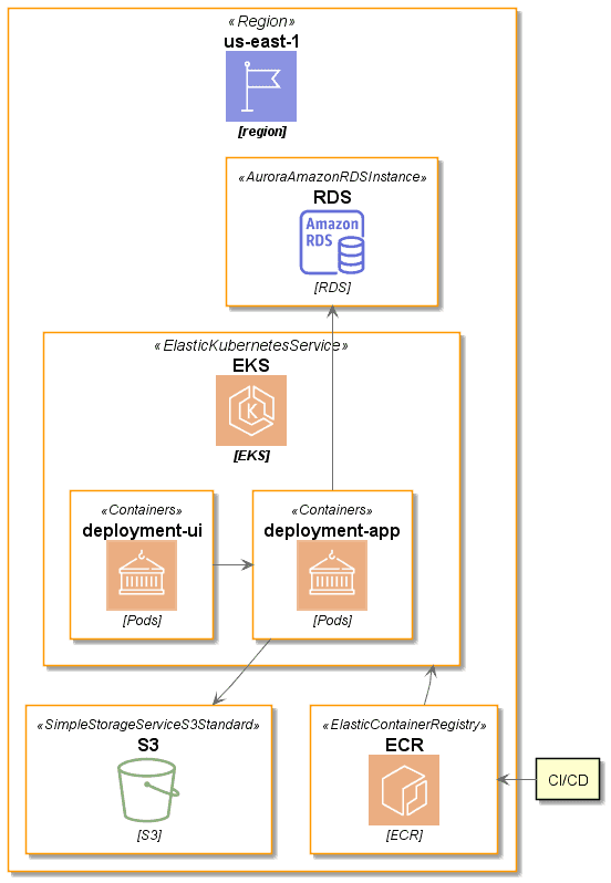
Let’s focus on only what the development team cares about
As a developer I care that my applications are getting deployed to EKS, they can talk to each other, that there’s an S3 bucket for myself, an RDS for my database, and yes good EKS is getting Docker images from that ECR over there. Great looks good yup that’s what I need.
Great, how do we do that with PlantUML?
Enter PlanUML pre-processor commands
In addition to its version control capability text means you can use common tools to pre or post process.
Thankfully we don’t even need to choose or write one: PlantUM has a built in pre-processor!
In this pre-processor language we can define variables, evaluate conditions, loop, include other files, lots of things.
For this work we just want to exclude parts of a diagram when a variable is true.
!if (includePerspective=="network")
Route53("ingress", "traffic ingress", "DNS")
!endif
The easiest way to set the includePerspective variable here is to use the PlantUML’s CLI to create them on the command line using -D arguments.
If our diagram is in input.plantuml we can set includePerspective using the following CLI command: plantuml -DincludePerspective=network input.plantuml
PlantUML’s preprocessor seems to only understand lines of code, not the structure behind them, so if you want to optionally pull away that VPC it looks kind of weird.
!if (includePerspective=="network")
  VirtualPrivateCloud("VPC", "VPC", "Amazon VPC") {
    ElasticLoadBalancingNetworkLoadBalancer("ELB", "ELB", "ELB")
    VPCSubnetPrivate("subnetOne", "subnet", "Private subnet") {
!endif
      ElasticKubernetesService("EKS", "EKS", "EKS") {
            Containers("deploymentUIPod", "deployment-ui", "Pods")
      }
!if (includePerspective=="network")
    }
  }
!endif
See how we contain the if around the VPC and ELB, then come back after the EKS cluster to close the braces?
The Big Diagram
@startuml

!define AWSPuml https://raw.githubusercontent.com/awslabs/aws-icons-for-plantuml/v11.1/dist
!includeurl AWSPuml/AWSCommon.puml

' Uncomment the following line to create simplified view
' !includeurl AWSPuml/AWSSimplified.puml

!includeurl AWSPuml/Compute/all.puml
!includeurl AWSPuml/ApplicationIntegration/APIGateway.puml
!includeurl AWSPuml/General/Internetalt1.puml
!includeurl AWSPuml/Database/DynamoDB.puml
!includeurl AWSPuml/NetworkingContentDelivery/Route53.puml
!includeurl AWSPuml/NetworkingContentDelivery/VirtualPrivateCloud.puml
!includeurl AWSPuml/GroupIcons/VPCSubnetPrivate.puml
!includeurl AWSPuml/GroupIcons/Region.puml
!includeurl AWSPuml/NetworkingContentDelivery/ElasticLoadBalancingNetworkLoadBalancer.puml
!includeurl AWSPuml/Containers/ElasticKubernetesService.puml
!includeurl AWSPuml/Containers/Containers.puml
!includeurl AWSPuml/Database/AuroraAmazonRDSInstance.puml
!includeurl AWSPuml/Containers/ElasticContainerRegistry.puml
!includeurl AWSPuml/Storage/SimpleStorageServiceS3Standard.puml


!if (includePerspective=="network")
Route53("ingress", "traffic ingress", "DNS")
!endif


Region("AWSRegion", "us-east-1", "region") {
!if (includePerspective=="network")
  VirtualPrivateCloud("VPC", "VPC", "Amazon VPC") {
    ElasticLoadBalancingNetworkLoadBalancer("ELB", "ELB", "ELB")
    VPCSubnetPrivate("subnetOne", "subnet", "Private subnet") {
!endif
      ElasticKubernetesService("EKS", "EKS", "EKS") {
            Containers("deploymentUIPod", "deployment-ui", "Pods")
!if (includePerspective=="network")
            rectangle "k8s ingress" as kIngress
!endif
            Containers("deploymentBackendPod", "deployment-app", "Pods")
      }
      AuroraAmazonRDSInstance("DB", "RDS", "RDS")
!if (includePerspective=="network")
     }
  }
!endif
ElasticContainerRegistry("ECR", "ECR", "ECR")
      SimpleStorageServiceS3Standard("S3Bucket", "S3", "S3")

}

rectangle "CI/CD" as CiCD

!if (includePerspective=="network")
ingress -> ELB
ELB -> kIngress
kIngress -> deploymentUIPod
!endif

deploymentUIPod -> deploymentBackendPod
deploymentBackendPod -u-> DB
ECR -u-> EKS
deploymentBackendPod -d-> S3Bucket
CiCD -> ECR
@enduml
Conclusion
It’s important to tailor a message to your audience, and using diagrams that can (a) be source controlled and (b) ran through a pre-processor (that isn’t M4 or a custom one you hacked together with 30 lines of PERL) is a great, if not well known, addition to your PlantUML toolkit.

